


© Copyright, Alliance Laundry Systems LLC – DO NOT COPY or TRANSMIT
Installation
513005
8
D337I
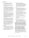
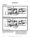
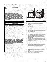
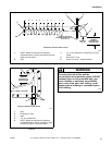
1 Closet Door
2 Centered Air Openings (G) (2 Openings
minimum)
3 Outer Wall of Enclosure
**NOTE: For new installations, locate top of wall vent 42 inches (106.7 cm) above floor to make venting
easier to connect.
Figure 4
D337I
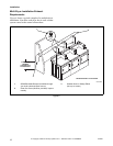
1
2 (G)
3
A
E
**42 in.
(106.7 cm)
F
F
B
AA
C
FRONT VIEW
(W/O CLOSET DOOR)
SIDE VIEW
(CLOSET DOOR)
FRONT VIEW
(CLOSET DOOR)
D
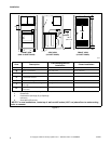
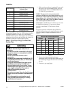
Area Description
Free Standing/Alcove
Installation
Closet Installation
A
Dryer sides and rear clearance 0 in. (0 cm) 0 in. (0 cm)
B
Dryer top clearance 12 in. (30.5 cm) 12 in. (30.5 cm)
C
Dryer front clearance Not Applicable 2 in. (5.1 cm)
D
Exhaust duct clearance to
combustible material
2 in. (5.1 cm) 2 in. (5.1 cm)
E
Weather hood to ground clearance 12 in. (30.5 cm) 12 in. (30.5 cm)
F
Distance from floor or ceiling to
hole edge
Not Applicable 3 in. (7.6 cm)
G*
Area of centered air openings in
closet door
Not Applicable 40 sq. in./open (260 sq. cm)
*Louvered door with equivalent air openings is acceptable. (Minimum clearances are shown.)